
A Practical Guide to Reticle Carrier Material Comparison
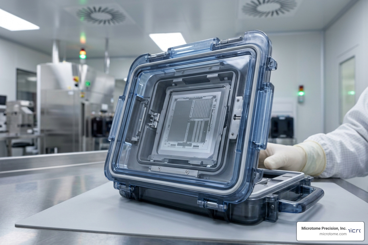
Why Reticle Carrier Material Determines Whether Your Photomask Survives
Choosing the right reticle carrier material is one of the most consequential decisions a fab or mask shop manager can make. Reticles can cost over a million dollars and take weeks to qualify — and the wrong carrier material can destroy them silently, through contamination, particle generation, or electrostatic damage that never triggers an obvious alarm.
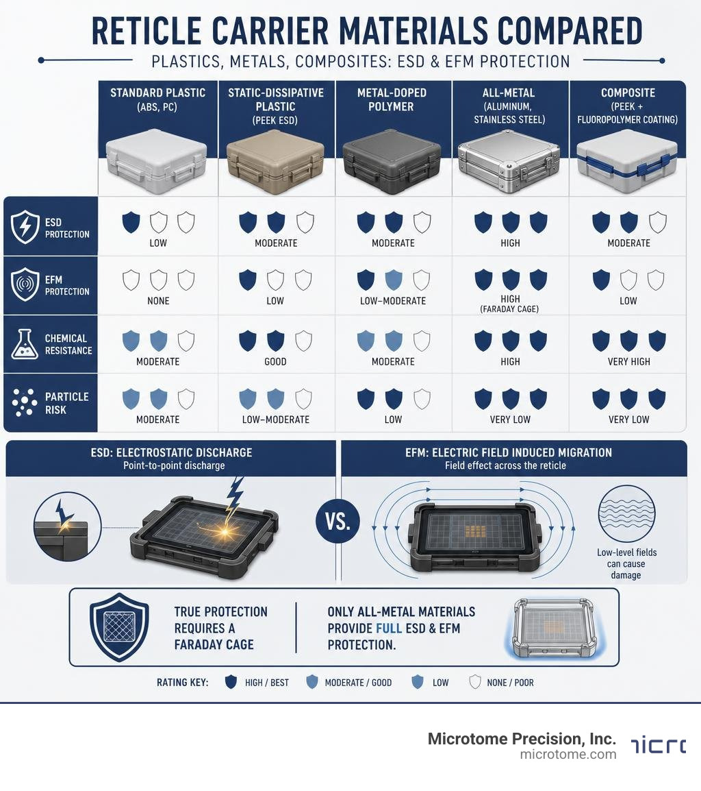
Here’s a quick-reference summary of the most common reticle carrier materials and what they protect against:
| Material | ESD Protection | EFM Protection | Chemical Resistance | Particle Risk |
|---|---|---|---|---|
| Standard plastic (ABS, PC) | Low | None | Moderate | Moderate |
| Static-dissipative plastic (PEEK ESD) | Moderate | Low | Good | Low-Moderate |
| Metal-doped polymer | Moderate | Low-Moderate | Moderate | Low |
| All-metal (aluminum, stainless steel) | High | High (Faraday cage) | High | Very Low |
| Composite (PEEK + fluoropolymer coating) | Moderate | Low | Very High | Very Low |
The core issue is this: not all protection is equal. Standard static-dissipative plastics may actually increase the risk of a damage mode called EFM (Electric Field induced Migration) — a failure mechanism that occurs at far lower electrostatic stress levels than conventional ESD. Only materials that form a true Faraday cage around the reticle fully block the electric fields responsible for EFM.
I’m Matt Pilarski, President of Microtome Precision, Inc., where we’ve been designing and manufacturing reticle carriers since 1989 — and our research team discovered and characterized EFM in 2003, which later informed the SEMI E163 standard for reticle carrier material selection and handling. In this guide, I’ll walk you through exactly how to evaluate and compare your options so you can make a confident, informed choice.
Key Performance Requirements for Reticle Carrier Material Selection
When evaluating any potential reticle carrier material, we must look beyond basic mechanical durability. The material is the primary interface between your high-value photomask and the external environment. It must perform flawlessly across several critical vectors.

Particle Generation and Shedding
In sub-10nm and EUV lithography, even a single nanometer-scale particle can ruin an entire wafer exposure run. The carrier material must possess extreme wear resistance to prevent particle shedding during robot handling, latching, and transport. Traditional polymers can experience microscopic abrasion at contact points, releasing particles that migrate onto the active area of the photomask.
Chemical Compatibility and Outgassing
Fabs use aggressive chemicals for mask cleaning and processing. Any material used in a reticle carrier must resist degradation from these chemicals. Furthermore, outgassing is a major threat. Volatile organic compounds (VOCs) released by inferior polymers can deposit onto the reticle surface. When exposed to high-energy lithography light (especially 193nm immersion or EUV), these compounds undergo photochemical reactions, forming “photochemical haze” that degrades imaging performance.
Electrostatic Discharge (ESD) and Field Shielding
Static electricity is the silent killer of photomasks. If a carrier accumulates charge, it can discharge directly into the reticle, vaporizing or delaminating the fine chrome or absorber patterns on the quartz substrate. To prevent this, materials are often classified into three categories:
- Electrically Isolating: Materials that hold charge and cannot dissipate it.
- Static Dissipative: Materials that slowly bleed off charges to ground.
- Electrically Conductive: Materials that rapidly conduct charges away.
While static-dissipative polymers help bleed off charges, they do not shield the reticle from external, transient electric fields. This is why testing carrier materials under real-world electrostatic stress is so critical. For deeper insights into managing these electrical risks, we recommend exploring our Electrostatic Protection Consultancy Service to evaluate your fab’s specific environment.
Durability and Mechanical Rigidity
Reticle carriers are subjected to continuous robotic gripping, conveyor transport, and vacuum cycles. If a carrier lid or base undergoes even minor creep deformation over time, it can compromise the airtight seal or lead to robotic alignment errors. The material must maintain its dimensions up to 180°C to withstand demanding cleaning and drying cycles without warping.
Fabs must also ensure compliance with SEMI standards (such as SEMI E111, E112, and E163), which govern the physical dimensions, interface points, and electrical properties of reticle handling systems. For academic validation of how carrier conductivity directly impacts mask safety, refer to the landmark study on Reticle carrier material as ESD protection .
Comparing Common Reticle Carrier Materials: Polymers vs. Metals
To make the best decision for your lithography bay, let’s break down the mechanical and electrical properties of the most common materials used in reticle carrier manufacturing.
Polyetheretherketone (PEEK) and ESD-Doped Polymers
PEEK is a high-performance thermoplastic widely appreciated for its exceptional mechanical strength, chemical resistance, and thermal stability. In its pure form, PEEK is highly insulating. To make it suitable for semiconductor environments, manufacturers often dope it with carbon fibers or carbon nanotubes, creating static-dissipative variations (like STAT-PRO 435). This provides a surface resistivity typically ranging from 10^3 to 10^9 ohm/sq, allowing controlled charge dissipation.
Acrylonitrile Butadiene Styrene (ABS) and Polycarbonate (PC)
Commonly used in budget-friendly single-reticle compacts or shipping boxes, ABS and polycarbonate are lightweight and easy to injection-mold. They can be made transparent, which is convenient for visual inspections. However, they suffer from higher outgassing rates and lower thermal resistance compared to PEEK. They are also prone to static charge accumulation unless coated with temporary antistatic agents, which can wear off and leave residues.
Carbon Fiber Composites
Carbon fiber offers unmatched strength-to-weight ratios and high rigidity. When used as a structural core, it prevents any physical sagging or bending of the carrier. It is inherently conductive, which helps with electrostatic dissipation, but it must be carefully sealed or combined with other polymers to prevent individual carbon micro-fibers from shedding and becoming particle contaminants.
Aluminum and Stainless Steel
Metals represent the gold standard for structural integrity and absolute electrostatic protection. An all-metal carrier, such as one milled from high-grade aluminum or stainless steel, acts as a perfect Faraday cage. Electric fields cannot penetrate a closed metal container; instead, they flow around the exterior shell to ground, leaving the reticle inside completely untouched by external voltage spikes.
Metals do not outgas, do not shed particles when properly finished, and can withstand extreme temperatures and aggressive solvent cleaning indefinitely. To see how different materials stack up against your specific process chemicals, check out our comprehensive compatibility guidelines.
Material Comparison Matrix
| Material Property | Polycarbonate / ABS | ESD-PEEK | Carbon Fiber | Anodized Aluminum |
|---|---|---|---|---|
| Tensile Strength | Low to Moderate | High | Very High | High |
| Max Operating Temp | ~80°C | ~180°C | >200°C | >300°C |
| Outgassing Risk | High | Low | Low | Zero |
| Particle Generation | Moderate | Low | Low (if sealed) | Zero |
| Electric Field Shielding | None | Low to Moderate | Moderate | Absolute (Faraday Cage) |
| Relative Cost | Low | High | Very High | Moderate to High |
Advanced Lithography and EUV Reticle Carrier Material Innovations
As the semiconductor industry pushes past the 3nm node, Extreme Ultraviolet (EUV) lithography introduces entirely new material challenges. EUV reticles do not use protective pellicles in the same way traditional DUV reticles do, meaning the active reflective multilayer surface is highly vulnerable to any particle larger than a few nanometers.
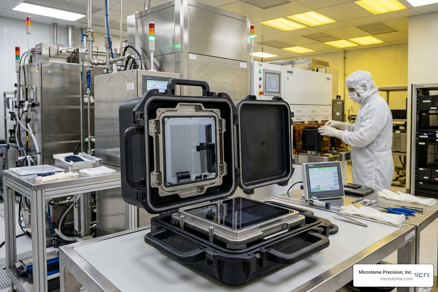
To solve this, advanced EUV reticle pods utilize a sophisticated dual-pod design consisting of an Inner Pod (inner carrier) and an Outer Pod (outer shell).
- The Outer Pod: Typically made of highly durable, ESD-safe polymers or metals, the outer shell interfaces with the fab’s automated material handling systems (AMHS) and overhead hoist transport (OHT). It protects the inner environment from external atmospheric contaminants, moisture, and physical shocks.
- The Inner Pod: This pod is transferred directly into the ultra-high vacuum chamber of the EUV lithography tool. Because it enters the vacuum chamber, the inner pod material must have virtually zero outgassing. It is often made of specialized metal alloys or ultra-clean, metal-doped PEEK to prevent any outgassing that could deposit onto the EUV optics.
Industry statistics prove the efficacy of these advanced designs. For example, testing has demonstrated that specialized EUV pods provide defect-free protection of EUV reticles during shipping, storage, handling, and vacuum-transferring operations down to 40 nm SiO2 equivalent particle sizes. This level of performance is critical for enabling high-volume manufacturing of advanced technology nodes.
These designs highlight the industry’s shift toward high-precision material engineering to meet stringent ASML and TSMC lithography requirements.
How to Select the Right Reticle Carrier Material for Your Fab
Selecting the perfect carrier material requires balancing your lithography node requirements, your chemical cleaning processes, and your budget. Here is a step-by-step approach to making the right choice.
Evaluating Reticle Carrier Material for ESD and EFM Prevention
While classic Electrostatic Discharge (ESD) involves a sudden spark jumping to the reticle, Electric Field induced Migration (EFM) is a more insidious threat. EFM occurs when a strong external electric field (for example, from a highly charged operator or a nearby plastic surface) induces a voltage potential across the fine metal lines on the photomask. This causes the metal (often chrome or molybdenum silicide) to migrate across the quartz substrate, causing sub-micron shorts and pattern distortions.
To prevent both ESD and EFM:
- Measure Surface Resistivity: Ensure your polymer carrier materials fall strictly within the static-dissipative range of 10^3 to 10^9 ohm/sq. Anything higher is too insulating; anything lower may conduct charges too abruptly.
- Verify Faraday Shielding: If your process involves transporting masks through areas with high ambient static charges, opt for an all-metal carrier. No plastic pod, even static-dissipative ones, can block external electric fields as effectively as a continuous metal shell.
- Perform CANARY Testing: Use sensitive CANARY (highly ESD-sensitive) test reticles to experimentally verify if your carrier material successfully shields against ambient fields during fast transport.
If you are looking for field-tested solutions designed specifically to eliminate these electrostatic failure modes, browse our complete range of Products Overview.
Assessing Reticle Carrier Material for Chemical and Thermal Stability
Your carrier must survive the harsh cleaning regimens used to strip organic residues and particulates.
- Review Outgassing Profiles: Ensure the material does not release volatile compounds that can lead to 193nm photochemical haze.
- Incorporate Purging Capabilities: For 193nm immersion lithography, select carriers that support clean dry air (CDA) or nitrogen (N2) purging. This active purging removes trace moisture and ozone, preventing haze formation on the reticle surface.
- Choose Composite Construction for Wet Processing: For carriers used during active chemical baths or megasonic cleaning, look for composite structures. A hard inner core made of carbon fiber, quartz, ceramic, or silicon carbide provides structural rigidity, while an outer fluoropolymer coating (such as PTFE, PFA, TFM, or ECTFE) ensures absolute chemical resistance and prevents sonic energy shadowing.
- Minimize Contact Mechanics: Choose carriers with angled slot walls (ideally 1-3 mm contact depth) to restrict contact exclusively to the non-patterned edges of the reticle.
To learn more about maintaining and recertifying your existing carrier fleet to preserve these critical properties, explore our specialized Support and Repair services. For an in-depth look at how advanced mechanical carriers are engineered to hold reticles securely during wet processing and polishing without inducing surface defects, you can read the details in this Reticle Carrier – Patent application .
Frequently Asked Questions about Reticle Carrier Materials
Why is ESD protection critical in reticle carrier material selection?
Photomasks feature incredibly fine, sub-micron metallic patterns deposited on an insulating quartz substrate. Because quartz is a non-conductor, any static charge introduced to the mask cannot easily dissipate. If the reticle carrier material does not provide a safe path to ground, a high-voltage electrostatic discharge (ESD) can occur. This rapid discharge can melt or vaporize the chrome patterns, rendering a million-dollar reticle instantly useless.
How do dual-pod designs improve contamination control in EUV lithography?
Dual-pod designs split the protective duties into two distinct layers. The outer pod acts as a rugged environmental shield, handling the physical wear and tear of automated robotic transport through the fab. The inner pod remains completely sealed inside the outer shell until it enters the lithography tool’s vacuum load lock. Because the inner pod is never exposed to the ambient cleanroom air or mechanical AMHS grippers, it remains free of airborne molecular contamination (AMC) and micro-particulates, ensuring defect-free vacuum transfer down to 40 nm particle thresholds.
What is the difference between EFM and ESD in reticle carriers?
ESD is a high-voltage, physical spark that occurs when two objects at different electrical potentials come into direct contact. EFM (Electric Field induced Migration), on the other hand, is caused by proximity to an electric field without any direct contact. Even if a reticle is floating inside a plastic carrier, a nearby charged object can project an electric field through the plastic. This field forces metal ions on the reticle to slowly migrate and form bridges between adjacent lines. EFM occurs at much lower electrostatic stress levels than ESD and can only be completely prevented by a conductive, all-metal Faraday cage.
Conclusion
In modern semiconductor manufacturing, your choice of reticle carrier material directly impacts your yield, your mask lifetime, and your bottom line. While lightweight polymers like PEEK and polycarbonate have their place in standard shipping and low-criticality operations, advanced lithography nodes demand absolute protection against both physical particles and invisible electrical fields.
At Microtome Precision, Inc., we believe that Reticle Protection is Our Business. Operating from our state-of-the-art facility in Colorado Springs, Colorado, we specialize in manufacturing all-metal reticle carriers that provide complete Faraday-cage protection. By choosing an all-metal design, you eliminate the risks of EFM, outgassing, and material degradation, ensuring your photomasks remain pristine through years of high-volume manufacturing.
Ready to upgrade your fab’s reticle protection strategy? Contact Microtome Precision today to consult with our engineering team and find the ideal carrier solution for your process.